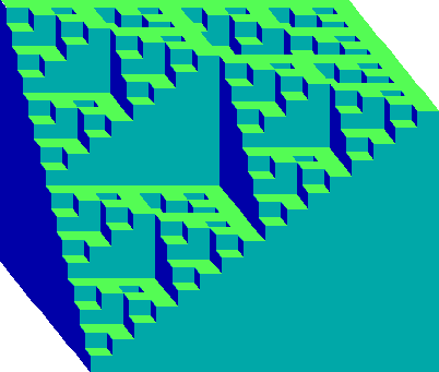
Fig. 27
Rather than graphing values in our value space in terms of color, the use of binary decimals makes it easy to graph them in terms of height in a third dimension. A value of .0000 will graph as 0, a value of .1000 as the decimal equivalent .5, .1100 as .75, and so forth.

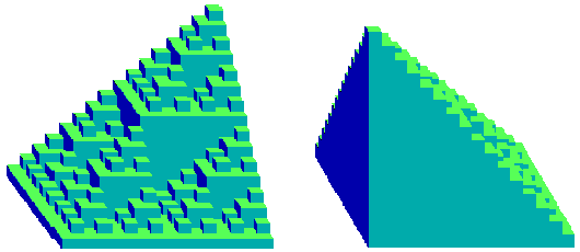
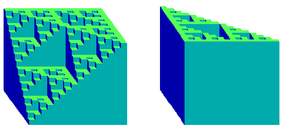
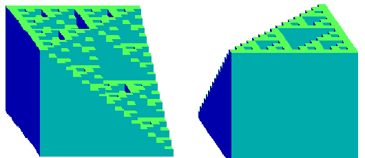
Fig. 29
These value solids make obvious the relationships between NAND and OR, the dual character of conjunction and disjunction, and the rotation properties of negation. Of perhaps deeper significance, however, these value solids for simple classical systems also show a striking resemblance to a very different type of solid that can be drawn for connectives within multi- valued or infinite-valued logics.
In this second type of solid, values on the axes represent not truth-table columns but degrees of truth. Within the value solid, height at a certain point represents the degree of truth of a complex of two sentences with the axis values of that point. In one standard treatment of infinite-valued connectives, for example, the value of a conjunction of sentences p and q is the minimum value of the two, represented as:
/p&q/ = min(p,q).The value solid of this type for conjunction will thus at each point have a height corresponding to the minimum of its axis values.
There are, however, rival sets of connectives that have been proposed for
multi-valued and infinite-valued or fuzzy logics. One such set, perhaps
most common within multi-valued and fuzzy logics, is shown in the left
column of Fig. 30. Another set, grounded more directly in the original
multi-valued logic of  ukasiewicz, is shown in the right
column.
Given that radical difference, the value solids outlined here for classical
systems and those sketched above for infinite-valued logics seem much more
alike than they have any right to be. Intriguingly, the system-solid for
each connective seems to be embody a compromise between the corresponding
infinite-valued connective solids. The system-solid for 'or', for example,
amounts neither to 'max' nor to the  ukasiewicz 'or'. It rather
appears to
be a compromise, in which some values correspond to one treatment of the
infinite-valued connective and one to another.
Indeed this is precisely what is happening. How it occurs--and why there is such a resemblance between these two radically different kinds of value solid--becomes clear if we return to two dimensions and consider a simple form of our basic value grid.
In a system grid for 'or', in which we are calculating the truth-table values for an 'or' between truth-table values on the axes, the value assigned to any intersection point is what might be called a 'bitwise or' of the values on the corresponding axes. A '1' occurs in any row in the value of that intersection point just in case a '1' occurs in that row in one or the other of the corresponding axis values. In bitwise 'or' the 1's cannot of course add together and carry to another row:
| p | q | (p or q) |
1 1 0 0 |
1 0 1 0 |
1 1 1 0 |
 ukasiewicz 'or',
to min (1, p+q). Nonetheless these three values for intersection points
will occasionally overlap.
In the simple case of three-digit binary decimals, in fact, where we take
111 as the closest approximation to 1 in the  ukasiewicz
formula, every
bitwise 'or' is equal to either max, the
  ukasiewicz 'or', or
both. This is
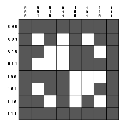
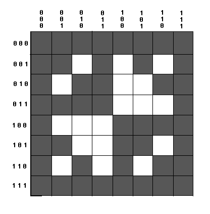
reflected in the 8 by 8 grids shown in Figure 31. On the first figure
those intersection points are mapped in which a bitwise 'or' corresponds to 'max'. On the second
are mapped those intersection points in the grid in which bitwise
'or' corresponds to the
  ukasiewicz 'or'. Here it is clear (a)
that the
middle areas, exclusive of the edges, are the negatives of each other, (b)
that together these two graphs will therefore cover the entire area of the
grid, and (c) that each middle area represents a simple Sierpinski gasket,
rotated 90 degrees from the other graph. A value solid for bitwise 'or'
geared to just three-digit binaries, then, would at each intersection point
correspond precisely to one or the other of the two infinite-valued
connectives outlined above: the 8-valued system solid constitutes a perfect
Sierpinski compromise between the two infinite-valued solids.
 ukasiewicz but greater
than simply 'max'.
Similar compromises hold in the case of the other connectives. Thus in an
intriguing way value-solids for simple systems do map a compromise between
the quite different value-solids appropriate to rival connectives within
infinite-valued or fuzzy logic.
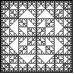
Fig. 32